
What is the working principle of flowmeters?
Leave a message

In the realm of industrial instrumentation, flowmeters play a pivotal role in measuring the flow rate of liquids, gases, or steam. As a trusted flowmeter supplier, I've witnessed firsthand the diverse applications and importance of these devices across various industries. In this blog post, I'll delve into the working principles of different types of flowmeters, shedding light on how they operate and their unique features.
Differential Pressure Flowmeters
Differential pressure (DP) flowmeters are among the most widely used types in the industry. The basic principle behind DP flowmeters is based on Bernoulli's equation, which states that as the velocity of a fluid increases, its pressure decreases. A DP flowmeter typically consists of a primary element, such as an orifice plate, venturi tube, or flow nozzle, and a differential pressure transmitter.
The primary element creates a constriction in the flow path, causing the fluid velocity to increase and the pressure to drop. The differential pressure transmitter measures the pressure difference between the upstream and downstream sides of the primary element. By knowing the relationship between the pressure difference and the flow rate, the flow rate can be calculated using a mathematical formula.
One of the advantages of DP flowmeters is their simplicity and wide range of applications. They can be used to measure the flow of various fluids, including liquids, gases, and steam. However, they also have some limitations, such as relatively high pressure drop, which can result in increased energy consumption, and the need for regular calibration to maintain accuracy.
Positive Displacement Flowmeters
Positive displacement (PD) flowmeters operate by trapping a known volume of fluid and then counting the number of times this volume is filled and emptied. The most common types of PD flowmeters include gear flowmeters, oval gear flowmeters, and rotary piston flowmeters.
In a gear flowmeter, two meshing gears are used to trap and transport the fluid. As the fluid enters the meter, it causes the gears to rotate. The rotation of the gears is proportional to the volume of fluid passing through the meter, and this rotation is detected by a sensor. The sensor then converts the rotation into an electrical signal, which can be used to calculate the flow rate.
PD flowmeters are known for their high accuracy, especially at low flow rates. They are also relatively insensitive to changes in fluid properties, such as viscosity and density. However, they are typically more expensive than other types of flowmeters and may require regular maintenance to ensure proper operation.
Turbine Flow Meters
A Turbine Flow Meter operates on the principle that the rotation speed of a turbine rotor is proportional to the flow rate of the fluid passing through it. The turbine rotor is placed in the flow path of the fluid, and as the fluid flows over the rotor blades, it causes the rotor to spin. The rotation of the rotor is detected by a sensor, such as a magnetic pickup or a Hall effect sensor, which generates an electrical signal proportional to the rotation speed.
The advantages of turbine flow meters include high accuracy, wide turndown ratio, and fast response time. They are commonly used in applications where accurate measurement of high flow rates is required, such as in the oil and gas industry, chemical processing, and water treatment. However, they are sensitive to changes in fluid viscosity and density, and the turbine rotor may be subject to wear and tear over time, which can affect the accuracy of the measurement.
Vortex Flowmeters
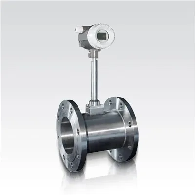
Vortex Flowmeter operate based on the principle of the von Kármán vortex street. When a fluid flows past a bluff body, such as a shedder bar, it creates a series of alternating vortices on the downstream side of the bluff body. The frequency of these vortices is proportional to the flow rate of the fluid.
A vortex flowmeter typically consists of a shedder bar, a sensor to detect the vortices, and an electronic transmitter to convert the vortex frequency into a flow rate measurement. The sensor can be a piezoelectric sensor, which generates an electrical signal when it is subjected to the pressure fluctuations caused by the vortices.
Vortex flowmeters are known for their reliability, wide rangeability, and low maintenance requirements. They can be used to measure the flow of liquids, gases, and steam over a wide range of flow rates. However, they may be affected by fluid turbulence and vibrations, which can cause errors in the measurement.
LDG Electromagnetic Flowmeters
The LDG Electromagnetic Flowmeter operates on the principle of Faraday's law of electromagnetic induction. According to Faraday's law, when a conductive fluid flows through a magnetic field, an electromotive force (EMF) is induced in the fluid. The magnitude of this EMF is proportional to the flow velocity of the fluid and the strength of the magnetic field.
An electromagnetic flowmeter consists of a flow tube, a pair of electrodes, and a magnetic coil. The flow tube is lined with a non-conductive material to prevent the electrical current from leaking out. The magnetic coil generates a magnetic field across the flow tube, and the electrodes are used to measure the induced EMF.
Electromagnetic flowmeters are ideal for measuring the flow of conductive liquids, such as water, wastewater, and slurries. They have several advantages, including high accuracy, no moving parts, and low pressure drop. However, they require the fluid to be conductive, and the accuracy of the measurement may be affected by changes in the conductivity of the fluid.
Ultrasonic Flowmeters
Ultrasonic flowmeters use ultrasonic waves to measure the flow rate of a fluid. There are two main types of ultrasonic flowmeters: transit-time flowmeters and Doppler flowmeters.
Transit-time flowmeters measure the difference in the time it takes for ultrasonic waves to travel upstream and downstream in the fluid. The upstream and downstream transit times are affected by the flow velocity of the fluid. By measuring the difference in these transit times, the flow velocity can be calculated.
Doppler flowmeters, on the other hand, measure the frequency shift of ultrasonic waves scattered by particles or bubbles in the fluid. The frequency shift is proportional to the flow velocity of the fluid.
Ultrasonic flowmeters are non-invasive, which means they can be installed on the outside of a pipe without the need to cut into the pipe. They are suitable for measuring the flow of both clean and dirty fluids. However, they may be affected by the presence of air bubbles or solids in the fluid, and the accuracy of the measurement may be limited at low flow rates.
Conclusion
In conclusion, there are several types of flowmeters available, each with its own working principle, advantages, and limitations. The choice of flowmeter depends on various factors, such as the type of fluid to be measured, the flow rate range, the required accuracy, and the installation conditions.
As a flowmeter supplier, I understand the importance of providing our customers with the right flowmeter for their specific applications. We offer a wide range of flowmeters, including differential pressure flowmeters, positive displacement flowmeters, turbine flow meters, vortex flowmeters, LDG electromagnetic flowmeters, and ultrasonic flowmeters. Our team of experts can help you select the most suitable flowmeter for your needs and provide you with professional installation, calibration, and maintenance services.


If you're looking for a reliable flowmeter supplier or have any questions about flowmeters, please don't hesitate to contact us. We're committed to providing you with high-quality products and excellent customer service. Let's work together to find the perfect flowmeter solution for your business.
References
- ISO 5167: Measurement of fluid flow by means of pressure differential devices inserted in circular cross-section conduits running full
- API MPMS Chapter 5: Flow Measurement
- ASME MFC-3M: Measurement of Fluid Flow in Closed Conduits Using Orifice, Nozzle, and Venturi