
How to calibrate the 3051 DP Transmitter?
Leave a message

Hey there! As a supplier of the 3051 DP Transmitter, I often get asked about how to calibrate these nifty devices. So, I thought I'd put together this blog post to share some tips and tricks on calibrating the 3051 DP Transmitter.
What is a 3051 DP Transmitter?
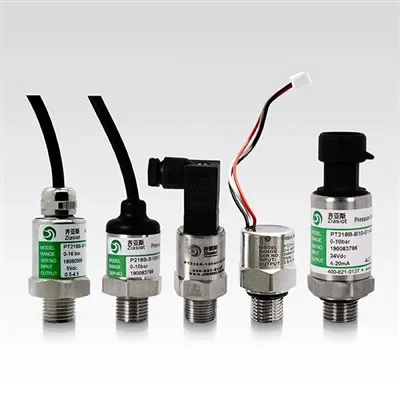
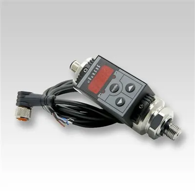
Before we dive into calibration, let's quickly go over what a 3051 DP Transmitter is. The 3051 DP Transmitter is a differential pressure transmitter that measures the difference in pressure between two points. It's commonly used in a variety of industries, including oil and gas, chemical, and power generation. These transmitters are known for their high accuracy, reliability, and durability, making them a popular choice for many applications.
Why Calibration is Important
Calibration is a crucial step in ensuring that your 3051 DP Transmitter is providing accurate and reliable measurements. Over time, factors such as temperature changes, vibration, and wear and tear can cause the transmitter to drift from its original calibration. This can lead to inaccurate readings, which can have serious consequences in industrial processes. By calibrating your transmitter regularly, you can maintain its accuracy and ensure that your processes are running smoothly.
Tools You'll Need
Before you start calibrating your 3051 DP Transmitter, you'll need to gather a few tools. Here's what you'll typically need:
- A pressure source: This could be a hand pump, a pressure regulator, or a calibrated pressure standard.
- A reference pressure gauge: This gauge should be more accurate than the transmitter you're calibrating.
- A multimeter: You'll use this to measure the output signal from the transmitter.
- A screwdriver or other tools for accessing the transmitter's adjustment screws.
Step-by-Step Calibration Process
Step 1: Prepare the Transmitter
First, make sure the transmitter is installed correctly and that all connections are tight. Turn off the power to the transmitter and disconnect the output signal wires. This will prevent any electrical interference during the calibration process.


Step 2: Zero Calibration
The first step in the calibration process is to perform a zero calibration. This ensures that the transmitter reads zero when there is no differential pressure applied.
- Apply zero differential pressure to the transmitter. You can do this by equalizing the pressure on both sides of the transmitter.
- Connect the multimeter to the output terminals of the transmitter. Set the multimeter to measure the appropriate current or voltage range, depending on the transmitter's output signal.
- Wait for the output signal to stabilize. Then, use a screwdriver to adjust the zero adjustment screw on the transmitter until the multimeter reads the correct zero output value. This value is typically 4 mA for a 4-20 mA output signal.
Step 3: Span Calibration
After completing the zero calibration, it's time to perform a span calibration. This ensures that the transmitter reads the correct value when the maximum differential pressure is applied.
- Apply the maximum differential pressure specified for the transmitter. You can use the pressure source to create this pressure.
- Wait for the output signal to stabilize. Then, use a screwdriver to adjust the span adjustment screw on the transmitter until the multimeter reads the correct full-scale output value. This value is typically 20 mA for a 4-20 mA output signal.
Step 4: Intermediate Point Check
To ensure the linearity of the transmitter, it's a good idea to check the output at one or more intermediate points between zero and full scale.
- Apply a known intermediate differential pressure to the transmitter.
- Measure the output signal with the multimeter. Compare the measured value to the expected value based on the linear relationship between pressure and output signal.
- If the measured value is outside the acceptable tolerance range, you may need to repeat the zero and span calibration steps.
Step 5: Final Checks
Once you've completed the calibration process, double-check all the connections and make sure everything is secure. Turn on the power to the transmitter and reconnect the output signal wires. Monitor the output signal for a few minutes to make sure it's stable and accurate.
Troubleshooting Common Issues
During the calibration process, you may encounter some common issues. Here are a few tips on how to troubleshoot them:
- Inaccurate Zero Reading: If the zero reading is off, check for leaks in the pressure connections. Make sure the pressure source is providing zero differential pressure. You may also need to clean the pressure ports or check for debris inside the transmitter.
- Inaccurate Span Reading: If the span reading is off, check the accuracy of the pressure source and the reference pressure gauge. Make sure the pressure applied is within the specified range for the transmitter. You may also need to adjust the span adjustment screw more carefully.
- Non-Linear Output: If the output signal is not linear, it could be due to a damaged or worn-out sensor. In this case, you may need to replace the sensor or the entire transmitter.
Conclusion
Calibrating your 3051 DP Transmitter is an important task that ensures the accuracy and reliability of your measurements. By following the steps outlined in this blog post and using the right tools, you can calibrate your transmitter like a pro. Remember to calibrate your transmitter regularly to maintain its performance and prevent any issues in your industrial processes.
If you're in the market for a high-quality 3051 DP Transmitter or need any assistance with calibration or troubleshooting, feel free to reach out to us. We're here to help you get the most out of your differential pressure measurement systems. You can also check out our Differential Pressure Sensor, Differential Pressure Sensor Hvac, and Diff Pressure Transmitter for more information on our products.
References
- Emerson Process Management. (20XX). 3051 DP Transmitter User Manual.
- Instrumentation Handbook. (20XX). Calibration of Differential Pressure Transmitters.