How to connect ceramic pressure transmitters to a control system?
Leave a message
Connecting ceramic pressure transmitters to a control system is a crucial process that requires careful planning and execution. As a dedicated supplier of high - quality Ceramic Pressure Transmitters, I understand the importance of seamless integration and the role it plays in ensuring the efficiency and reliability of various industrial applications.
1. Understanding Ceramic Pressure Transmitters
Before we delve into the connection process, it's essential to understand what ceramic pressure transmitters are and why they are widely used. Ceramic pressure transmitters are devices designed to measure pressure and convert it into an electrical signal. They operate based on the principle of piezoresistivity, where the resistance of a ceramic material changes in response to applied pressure.
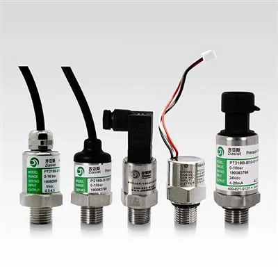
These transmitters offer several advantages, including high accuracy, excellent long - term stability, and resistance to corrosion. They are suitable for a wide range of applications, from industrial processes to HVAC systems. Our company offers different types of ceramic pressure transmitters, such as Refrigeration Pressure Transmitter, Standard Ceramic Pressure Transmitter, and Anti - Crossive Pressure Transmitter, each tailored to specific industry needs.
2. Pre - connection Preparations
2.1 Selecting the Right Transmitter
The first step is to select the appropriate ceramic pressure transmitter for your control system. This decision depends on various factors, such as the pressure range, accuracy requirements, and the type of medium being measured. For example, if you are dealing with refrigeration systems, the Refrigeration Pressure Transmitter would be a suitable choice due to its compatibility with refrigerants.
2.2 Checking the Control System Requirements
Understand the input requirements of your control system. This includes the type of signal it can accept (e.g., analog or digital), the voltage or current range, and the communication protocol. Make sure that the output signal of the ceramic pressure transmitter is compatible with the control system.
2.3 Gathering Necessary Tools and Materials
You will need some basic tools for the connection process, such as screwdrivers, wire strippers, and electrical tape. Additionally, prepare the appropriate cables and connectors according to the specifications of the transmitter and the control system.
3. Physical Installation of the Transmitter
3.1 Mounting the Transmitter
Choose a suitable location to mount the ceramic pressure transmitter. It should be close to the point where pressure needs to be measured to minimize pressure losses. Ensure that the mounting surface is flat and clean. Use the mounting hardware provided with the transmitter to secure it firmly.
![]()
![]()
3.2 Connecting the Pressure Port
Connect the pressure port of the transmitter to the pressure source. This may involve using appropriate fittings and seals to prevent leaks. Make sure that the connection is tight and that there are no obstructions in the pressure path.
4. Electrical Connection
4.1 Signal Output Wires
Identify the signal output wires of the ceramic pressure transmitter. Typically, these wires are color - coded to indicate the type of signal (e.g., +V for power supply, -V for ground, and Sig for the pressure signal). Carefully strip the insulation from the ends of the wires using a wire stripper.
4.2 Connecting to the Control System Input
Connect the signal output wires of the transmitter to the corresponding input terminals of the control system. Follow the wiring diagram provided by both the transmitter and the control system manufacturers. Make sure that the connections are secure and that there is no short - circuiting.
4.3 Power Supply Connection
Connect the power supply wires of the transmitter to a suitable power source. Ensure that the voltage and current ratings of the power source match the requirements of the transmitter. Use electrical tape to insulate the connections and prevent any electrical hazards.
5. Configuration and Calibration
5.1 Configuration
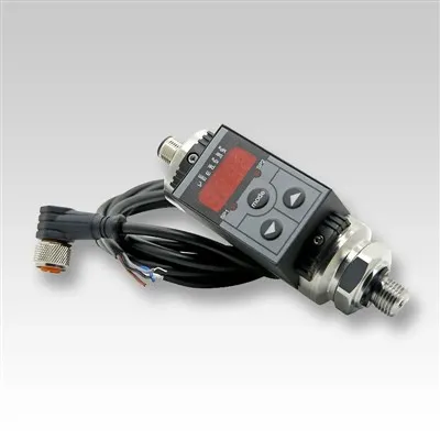
Once the physical and electrical connections are complete, configure the ceramic pressure transmitter according to your application requirements. This may involve setting parameters such as the pressure range, output signal type, and communication settings. Refer to the user manual of the transmitter for detailed configuration instructions.
5.2 Calibration
Calibration is a critical step to ensure the accuracy of the pressure measurements. Use a calibrated pressure reference device to compare the output of the transmitter with the known pressure values. Adjust the calibration settings of the transmitter until the measured values match the reference values within the desired accuracy range.
6. Testing the Connection
6.1 Initial Checks
Before powering on the entire system, perform a visual inspection of all the connections to ensure that there are no loose wires or incorrect connections. Check the power supply voltage to make sure it is within the specified range.
6.2 Power - on Testing
Power on the control system and the ceramic pressure transmitter. Monitor the output signal of the transmitter on the control system display. Apply a known pressure to the transmitter and verify that the measured pressure value on the control system matches the applied pressure.
6.3 System - level Testing
Conduct system - level testing to ensure that the pressure transmitter and the control system work together effectively. This may involve simulating different pressure conditions and observing the response of the control system. Check for any abnormal behavior or errors during the testing process.
7. Troubleshooting
7.1 Signal Issues
If you encounter problems with the signal output, such as no signal or incorrect readings, first check the electrical connections. Make sure that the wires are properly connected and that there are no shorts or open circuits. Also, check the power supply to ensure that the transmitter is receiving the correct voltage.
7.2 Pressure Measurement Errors
If the pressure measurements are inaccurate, it could be due to improper calibration or a problem with the pressure port connection. Check the calibration settings and recalibrate the transmitter if necessary. Inspect the pressure port for any leaks or blockages.
7.3 Communication Problems
If you are using a digital communication protocol, communication problems may occur. Check the communication settings of both the transmitter and the control system. Make sure that the baud rate, parity, and other communication parameters are correctly configured.
Connect with Us for Your Purchasing Needs
Connecting ceramic pressure transmitters to a control system is a multi - step process that requires attention to detail and technical expertise. As a leading supplier of Ceramic Pressure Transmitters, we are committed to providing you with high - quality products and comprehensive technical support.
If you are in the market for ceramic pressure transmitters or need further assistance with the connection process, we invite you to reach out for a purchase negotiation. Our team of experts is ready to help you select the most suitable products for your specific requirements and ensure a seamless integration into your control system.
References
- "Industrial Pressure Transmitter Handbook", Publisher: ABC Press, Year: 20XX
- "Ceramic Pressure Sensor Technology", Author: John Doe, Journal: Sensor Science, Volume: XX, Issue: XX, Year: 20XX