Differential Pressure Flow Meters Have A Wide Range Of Applications
Leave a message
Differential pressure flow meters have a wide range of applications. Various objects have applications in flow measurement of closed pipelines. In terms of fluids: single-phase, mixed phase, clean, dirty, viscous flow, etc; In terms of working conditions: atmospheric pressure, high pressure, vacuum, normal temperature, high temperature, low temperature, etc; In terms of pipe diameter: from a few millimeters to several meters; In terms of flow conditions: subsonic, supersonic, pulsating flow, etc. It accounts for approximately 1/4 to 1/3 of the total usage of flow meters in various industrial sectors.
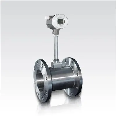
1. Commonly used standard throttling devices (orifice plates), (nozzles), and (Venturi tubes).
2. Common non-standard throttling devices include (double orifice plate), (round missing orifice plate), (1/4 round nozzle), and (Venturi nozzle).
3. The commonly used pressure measurement methods for orifice plates include (corner connection pressure measurement) and (flange pressure measurement), while other methods include (theoretical pressure measurement), (radial distance pressure measurement), and (pipe connection pressure measurement).
4. The standard orifice flange pressure measurement method has a distance of (25.4 ± 0.8) mm between the center of the upstream and downstream pressure measurement holes and the front and rear end faces of the orifice plate, also known as 1-inch flange pressure measurement.
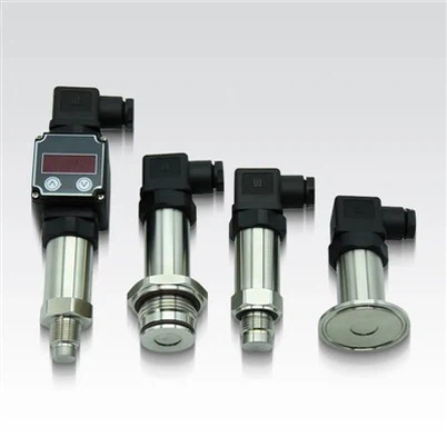
5. The working power range of the 1151 transmitter is (12) vdc to (45) vdc, and the load ranges from (0) ohms to (1650) ohms.
6. The measurement range of the 1151dp4e transmitter is (0-6.2) to (0-37.4) kPa.
7. The maximum positive migration of 1151 differential pressure transmitter is (500%), and the maximum negative migration is (600%).
8. The fluid velocity inside the pipeline is generally the highest at the centerline of the pipeline, and the velocity at the wall is equal to zero.
9. If the Reynolds number is the same, the motion of the fluid is similar.
10. When the fluid filled with the pipeline flows through the throttling device, the flow beam will undergo (local contraction) at the (constriction), resulting in an increase in (flow velocity) and a decrease in (static pressure).
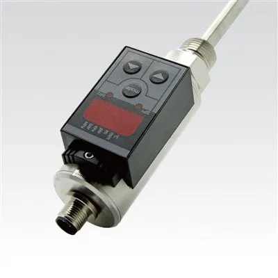
11. The 1151 differential pressure transmitter uses variable capacitors as sensitive components. As the differential pressure increases, the measuring diaphragm shifts, resulting in an increase in capacitance on the low voltage side and a decrease in capacitance on the high voltage side
12. When using the minimum calibration range of the 1151 differential pressure transmitter, the maximum load migration is (600%) of the range, and the maximum positive migration is (500%). If using the maximum calibration range of 1151, the maximum negative migration is (100%), and the maximum positive migration is (0%).
13. The accuracy of the differential pressure transmitter in 1151 [4] is (± 0.2%) and (± 0.25%). Note: The large differential pressure transmitter is ± 0.25%
14. The commonly used flow units and volumetric flow rates are (m3/h) and (t/h), while the mass flow rates are (kg/h) and (t/h). Under standard conditions, the gas volumetric flow rate is (nm3/h).
15. Using an orifice flowmeter to measure steam flow rate, when designed, the density of steam is 4.0kg/m3, but in actual operation, the density is 3kg/m3. Therefore, the actual indicated flow rate is (0.866) times the design flow rate.
16. Using an orifice flowmeter to measure the ammonia flow rate, the design pressure is 0.2 MPa (gauge pressure) and the temperature is 20 ℃. However, if the actual pressure is 0.15 MPa (gauge pressure) and the temperature is 30 ℃, the actual indicated flow rate is (0.897) times the design flow rate.
17. The straight pipe section in front of the orifice plate generally requires (10) d, and the straight pipe section behind the orifice plate generally requires (5) d. In order to measure correctly, it is best to have a straight pipe section in front of the orifice plate of (30-50) d, especially when there is a pump or regulating valve in front of the orifice plate.
18. In order to improve the flow coefficient of the orifice flowmeter α Towards a constant value, the Reynolds number of the fluid should be greater than (the boundary Reynolds number).
19. In the technical requirements for orifice plate processing, the upstream plane should be perpendicular to the centerline of the orifice plate, without visible scratches. The upstream and downstream surfaces should be parallel, and the upstream inlet edge should be sharp and free of burrs and scratches.