
Troubleshooting Guide For Submersible Level Transmitter
Leave a message
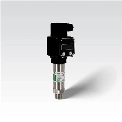
Submersible level transmitters are precision instruments designed to measure hydraulic pressure. These devices feature advanced oil-filled sensing elements housed in stainless steel enclosures, converting static pressure into electrical signals. Through integrated microsignal processing circuits, the measurements are transformed into industry-standard 4–20 mA DC current outputs (two-wire configuration).


This guide outlines four common failure modes and their respective solutions to facilitate rapid on-site diagnostics and ensure proper operation of submersible level transmitters.
1. Fault: No Output Signal
Root Causes & Solutions:
✔Verify proper polarity and connection of power terminals.
✔Ensure wiring matches the transmitter's terminal designations.
✔Measure supply voltage: Must be 24 VDC ±10% (21.6–26.4 VDC).
✔Check for open circuits or excessive load impedance (≤500 Ω at secondary devices like PLCs).
✔Tighten terminal screws to eliminate contact resistance.
2. Fault: Output Signal ≥20 mA or ≤4 mA
Diagnostic Steps:
✔Confirm power supply is within 24 VDC ±10%. Overvoltage can damage components.
✔Assess if the measured level exceeds the transmitter's full-scale range. Replace with a suitable model if necessary.
✔Inspect the isolation diaphragm for deformation or rupture caused by overpressure or mechanical impact. Return for repair if compromised.
✔Recheck terminal connections and ensure no miswiring exists (e.g., power lines connected to signal terminals).
3. Fault: Inaccurate or Erratic Output
Resolution Protocol:
✔ Stabilize supply voltage to 24 VDC ±10% and minimize load fluctuations.
✔ Calibrate the secondary device (e.g., PLC, display) to match the transmitter's specified range (e.g., 0–10 mH₂O).
✔ Separate high-voltage (AC) and low-voltage (DC) cables to reduce electromagnetic interference (EMI). Use shielded cables for signal lines.
✔ Detect membrane damage from overpressure or contaminants. Return for recalibration if abnormalities are found.
✔ Remove debris from the pressure port and install a sintered filter to prevent clogging.
4. Fault: Zero Drift or Long-Term Instability
Proactive Measures:
✔ Account for ambient temperature effects, especially in outdoor applications.
✔ Schedule annual recalibration and diaphragm inspections.
✔ Avoid mounting near vibration sources or in turbulent media.
Key Takeaways
✔ Prevention: Regular calibration and proper installation reduce 80% of field failures.
✔ Critical Checks: Always verify power supply, wiring, and range compatibility before assuming hardware faults.
✔ Safety: For diaphragm damage or electrical issues, consult the manufacturer for repair.
For persistent issues, refer to the device's SIL 2/3 certification guidelines (IEC 61508) or contact technical support.