How do open - channel flowmeters work?
Leave a message
Open-channel flowmeters play a crucial role in various industries where measuring the flow of liquids in open channels is essential. As a leading supplier of flowmeters, we understand the importance of accurate flow measurement and the diverse applications that rely on it. In this blog post, we will delve into the working principles of open-channel flowmeters, exploring the different types and their applications.
Understanding Open-Channel Flow
Before we dive into how open-channel flowmeters work, it's important to understand what open-channel flow is. Open-channel flow refers to the flow of liquid in a conduit with a free surface, such as a river, canal, or sewer. Unlike closed pipes, where the liquid is under pressure, open-channel flow is driven by gravity. The flow rate in an open channel depends on several factors, including the channel's cross-sectional area, slope, and the roughness of the channel walls.
Types of Open-Channel Flowmeters
There are several types of open-channel flowmeters available, each with its own working principle and advantages. Here are some of the most common types:
Ultrasonic Flowmeters
Ultrasonic open-channel flowmeters use ultrasonic waves to measure the flow rate. They typically consist of two transducers, one upstream and one downstream. The transducers send and receive ultrasonic signals across the channel. The time it takes for the signals to travel between the transducers is affected by the flow velocity of the liquid. By measuring the difference in the transit time of the ultrasonic signals traveling upstream and downstream, the flow velocity can be calculated. Once the flow velocity is known, the flow rate can be determined by multiplying the velocity by the cross-sectional area of the channel.
Ultrasonic flowmeters are non-intrusive, which means they do not come into direct contact with the liquid. This makes them suitable for measuring the flow of corrosive or abrasive liquids. They are also highly accurate and can be used in a wide range of flow conditions.
Radar Flowmeters
Radar open-channel flowmeters use radar technology to measure the flow rate. They emit radar waves towards the surface of the liquid in the channel. The radar waves are reflected off the liquid surface, and the time it takes for the waves to return to the sensor is measured. By analyzing the frequency shift of the reflected radar waves, the flow velocity of the liquid can be determined. Similar to ultrasonic flowmeters, the flow rate is then calculated by multiplying the flow velocity by the cross-sectional area of the channel.
Radar flowmeters are ideal for measuring the flow of liquids with a dirty or turbulent surface. They are also unaffected by changes in the liquid's temperature, pressure, or conductivity.
Weirs and Flumes
Weirs and flumes are structures that are installed in open channels to measure the flow rate. A weir is a barrier placed across the channel, causing the liquid to flow over it. The height of the liquid above the weir is directly related to the flow rate. By measuring the head (the height of the liquid above the weir), the flow rate can be calculated using established equations.
Flumes, on the other hand, are specially shaped channels that constrict the flow of the liquid. The constriction causes a change in the flow velocity and depth, which can be used to calculate the flow rate. Weirs and flumes are relatively simple and cost-effective flow measurement devices. However, they require careful installation and calibration to ensure accurate measurements.
Working Principles in Detail
Let's take a closer look at the working principles of these open-channel flowmeters.
Ultrasonic Flowmeters
As mentioned earlier, ultrasonic flowmeters rely on the transit time difference of ultrasonic signals traveling upstream and downstream. The basic principle can be explained as follows:
- The upstream transducer emits an ultrasonic signal towards the downstream transducer. The time it takes for the signal to reach the downstream transducer is affected by the flow velocity of the liquid. If the liquid is flowing in the same direction as the signal, the transit time will be shorter. Conversely, if the liquid is flowing against the signal, the transit time will be longer.
- The downstream transducer then emits an ultrasonic signal towards the upstream transducer. By comparing the transit times of the upstream and downstream signals, the flow velocity can be calculated using the following formula:
[v=\frac{L}{2\cos\theta}\left(\frac{1}{t_d}-\frac{1}{t_u}\right)]
where (v) is the flow velocity, (L) is the distance between the transducers, (\theta) is the angle between the ultrasonic path and the flow direction, (t_d) is the transit time of the downstream signal, and (t_u) is the transit time of the upstream signal.
Once the flow velocity is determined, the flow rate (Q) can be calculated by multiplying the velocity by the cross-sectional area (A) of the channel:
[Q = v\times A]


Radar Flowmeters
Radar flowmeters operate based on the Doppler effect. When the radar waves are reflected off the moving liquid surface, the frequency of the reflected waves changes. This frequency shift is proportional to the flow velocity of the liquid. The basic steps involved in measuring the flow rate using a radar flowmeter are as follows:
- The radar sensor emits a continuous wave of radar energy towards the liquid surface.
- The radar waves are reflected off the moving liquid surface, and the reflected waves are received by the sensor.
- The sensor analyzes the frequency shift of the reflected waves to determine the flow velocity.
- Similar to ultrasonic flowmeters, the flow rate is calculated by multiplying the flow velocity by the cross-sectional area of the channel.
Weirs and Flumes
Weirs and flumes work based on the relationship between the head (the height of the liquid above the weir or flume) and the flow rate. For a rectangular weir, the flow rate can be calculated using the following formula:
[Q = C_d\times L\times H^{3/2}]
where (Q) is the flow rate, (C_d) is the discharge coefficient, (L) is the length of the weir, and (H) is the head above the weir.
For a Parshall flume, the flow rate can be determined using a set of calibration curves or equations that relate the head at a specific point in the flume to the flow rate.
Applications of Open-Channel Flowmeters
Open-channel flowmeters are used in a wide range of applications, including:
- Water and Wastewater Management: In water treatment plants, open-channel flowmeters are used to measure the flow of raw water, treated water, and wastewater. They help in monitoring the efficiency of the treatment processes and ensuring compliance with environmental regulations.
- Irrigation Systems: In agriculture, open-channel flowmeters are used to measure the flow of water in irrigation canals. This helps in optimizing water usage and ensuring that crops receive the right amount of water.
- Industrial Processes: Many industries, such as mining, chemical, and food processing, use open-channel flowmeters to measure the flow of liquids in their processes. This helps in controlling the production process and ensuring product quality.
Our Flowmeter Products
As a flowmeter supplier, we offer a wide range of open-channel flowmeters to meet the diverse needs of our customers. Some of our popular products include:
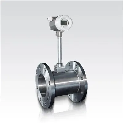
- Vortex Flowmeter: Our vortex flowmeters are designed to measure the flow of liquids, gases, and steam in both open channels and closed pipes. They are based on the principle of vortex shedding and offer high accuracy and reliability.
- LDG Electromagnetic Flowmeter: Our LDG electromagnetic flowmeters are suitable for measuring the flow of conductive liquids in open channels. They are non-intrusive and offer excellent accuracy and stability.
- Turbine Flow Meter: Our turbine flow meters are used to measure the flow of liquids in open channels and pipes. They are based on the principle of a rotating turbine and offer high accuracy and a wide flow range.
Contact Us for Your Flowmeter Needs
If you are looking for reliable and accurate open-channel flowmeters for your application, look no further. Our team of experts is ready to assist you in selecting the right flowmeter for your needs. We offer high-quality products, competitive prices, and excellent customer service. Contact us today to discuss your requirements and start a procurement negotiation.
References
- Chow, V. T. (1959). Open-Channel Hydraulics. McGraw-Hill.
- Bos, M. G. (1976). Discharge Measurement Structures. IHE Delft Institute for Water Education.
- Miller, R. W. (1983). Flow Measurement Engineering Handbook. McGraw-Hill.